The precision required for tube bending and other types of tube processing, such as laser tube cutting, tube rolling and tube welding, means that the characteristics of the processing to be carried out need to be communicated by the customer in a clear and generally understandable manner.
The industry-standard means of communication between the customer and the tube bending company is the technical drawing.
What is a technical drawing?
The technical drawing forms the basis for tube bending and other types of tube processing like roll bending, laser tube cutting or tube welding. A technical drawing is based on rules and standards, and is a medium of information. Such a drawing can be produced as a paper or digital document.
The technical drawing originated in the late Middle Ages and was developed during the Renaissance to overcome two major limitations of verbal communication:
- Guaranteeing the precise transmission of information
- Avoiding incorrect technical implementation resulting from faulty information and/or individual (arbitrary) interpretation of the information
Why is the technical drawing important?
The existence of a technical drawing for tube bending or any other type of tube processing is essential for the following reasons:
- It is a prerequisite for the initial feasibility analysis of the tube bending process
- It ensures the dimensions of the bent tube can be determined
- It provides information about the tube processing to be carried out
In the cold forming of steel tubes, the technical drawing guarantees the following:
- Avoidance of errors, misunderstandings and delays in tube processing
- Negotiations and communications between the client and the tube bending company
→ The technical drawing is an indispensable source of information, as it contains the details required for the machining and bending of metal tubes in steel, aluminium or stainless steel.
Tube bending and the technical drawing: what information should be included?
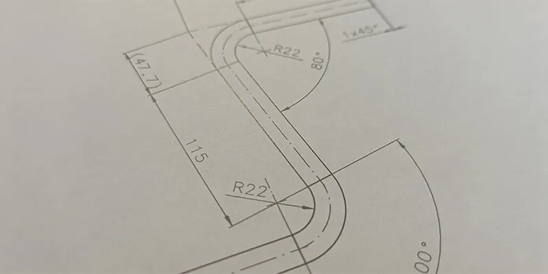
To assess the feasibility of a tube bending assignment, the following information must be known:
- Orthogonal tube projections
- Dimensions (dimensions, bend radiuses, bend angles, tube cross-sections)
- Permitted tolerances for the main ratios
- Metal alloy: is the tube to be bent made from aluminium, steel or stainless steel?
- Tube machining
- Type of tube welding
→ The dimensions must be measurable with commercially available measuring instruments, e.g:
- Caliper gauge
- Flexometer
- Digital height gauge
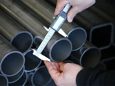
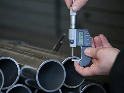
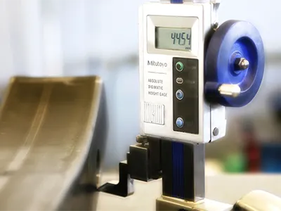
Digital tools for determining the dimensions of a bent tube (from left to right): caliper gauge, flexometer and height gauge.
Some dimensions may seem unimportant at first glance, but they are essential for the production of the bent tube. Alongside the technical drawing in PDF format, in which the client specifies the dimensions that are important to them, files in DXF/DWG (CAD) and 3D formats are also required, as these formats often contain other information that is needed to define and measure a dimension.
As one example, precise information about the straight tube section between two bends, which is crucial to understanding the feasibility of the bend, is not always available from the PDF drawing. However, it can always be extracted from a DXF file.
Information about the straight, unbent section of the tube between two bends is essential, as the size of the tube will determine whether or not special equipment is required for this procedure.
The section label: a ‘window’ with important information
The drawing alone does not provide all of the information that is needed to bend a metal tube or section.
For example, the drawing does not contain any information about the metal of the tube to be bent: is it steel, aluminium or stainless steel?
This lack of information is compensated for by another fundamental element that must be present on each sheet of the technical drawing: the section label.
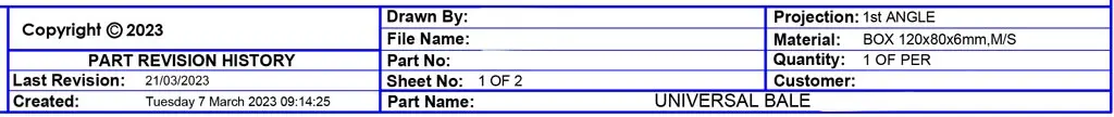
The section label is a text field located in one corner of the drawing, usually in the lower right corner. This field contains important information for processing the tube. The most important items of information are as follows:
- Metal alloy the tube is made from (e.g. steel S235).
- Author of the drawing
- Drawing review
The technical office: role and importance
The customer is not the only party who provides technical drawings.
Usually, the customer sends the drawing of the bent and finished tube but not the information about the tube processing that is required to produce the bent tube as required.
Very often, the tube has to be laser cut or drilled before bending.
For laser cutting, the laser operator needs a technical drawing of the straight (unbent) tube section with all the necessary dimensions and data specific to the laser cutting process.
This job of providing this ‘missing’ technical information is completed by the technical office, which produces the drawings for the machining operations relevant to tube bending or roll bending. In many cases, the tube will be machined with a laser tube cutting machine.
From the starting-point of the customer’s original drawing, the technical office produces one or more additional drawings that show all of the tube machining operations required before and after bending.
This is therefore a set of internal documents with dimensions, which list all of the machining operations to be carried out on the tube before bending. In the case of laser tube machining, this includes the following operations:
- Bores
- Diagonal cuts
- Markings
In some cases, additional technical drawings will be needed to supplement the customer’s drawings:
- When producing special parts such as bent sheets. In this case, the technical drawing is sent to the subcontractors.
- When performing accessory tube processing, such as tube milling, turning or welding
What happens if the information needed is unavailable?
The lack of information in a technical drawing – or, as is sometimes the case, the lack of a specific technical drawing – can lead to various problems:
- Inability to complete a feasibility study for the tube machining
- Doubts and ambiguities regarding the tube machining that must be clarified with the customer, leading to higher costs
- Delays to the quotation or non-delivery of the order
- Disagreement between the customer and the supplier about the tolerances for the bent or rolled tube, with the supplier considering the tolerances to be correct (according to the drawing and their own tolerance specifications) while the customer complains about certain defects. The problem is that the tolerances have not been specified in the drawing!
As a general rule, a customer should always provide complete drawings in accordance with ISO standards. Factors such as a lack of time or the simplicity of the tube bending work often mean that the customer only sends a rough drawing to the tube bending company to obtain a low-cost quotation.
Case study: what we experienced without a well-prepared technical drawing
There are numerous cases involving problems caused by a lack of clear information in the technical drawing. Here is a specific example.
The customer supplied a drawing without any tolerances for the external dimensions of the tube to be bent.
In this case, Tecnocurve bent the tube using standard tolerances (+/–2 mm), while the customer actually wanted a tolerance of +/–1 mm, although this was not specified in the drawing dimensions.
The solution was to use a control device to perform an additional deburring step.
This had two consequences:
- Increase in tube machining costs
- Increase in working time for tube bending
This problem would not have arisen if the technical drawing had included an explicit reference to the tolerances required by the customer.
Tubing bending: technical drawing formats
In the world of tubing bending, the customer must always provide a technical drawing to ensure an optimal and timely result for the bent tube. The main formats are as follows:
- Drawing with dimensions in PDF format
- Drawing in DWG/DXF format
- Drawing in 3D format for tubes with complex geometric shapes
Conclusions
A technical drawing can be compared to an instruction manual: the drawing contains information, such as tolerance data, that is necessary to define the dimensions for the correct sequence of tube bending with tube forming.
The technical drawing is also indispensable for another reason: the calculation formula required for the feasibility of tube bending can only be computed with the information that it contains, together with the bending radius.